Configuring a multi-ip|engine Router Data Center through iBGP - First Deployment
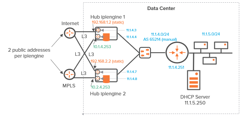
This first Data Center deployment uses two ip|engines with the same AS in the same subnet without access to the Core Router. It ensures network connectivity. It is complementary to "Use Case 2".
This configuration is done on the LAN panel of each ip|engine.

Graph legend
|
|
|
|
|
|
|
Grey connection |
|
ip|engine |
router |
switch |
subnet |
host in a subnet |
server |
connection between devices |
Note: A router may be a CE Router (MPLS Router), an Internet Access Router or a Core Router.
| 1 | After you have defined the interfaces of the Data Center second hub ip|engine (see "Router Mode"), configure its LAN. On "Use Case 4A" diagram, LAN information is displayed in blue. |

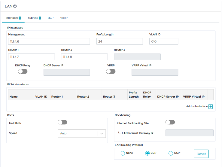
| 2 | Click the Interfaces tab. |
| • | Enter the ip|engine Management IP Address (11.1.4.6), Prefix Length (24). The Management IP address is used for communicating with other ip|engines, the ZTP Server and the Orchestrator. |
| • | Use the default Auto Generated option (creation window only) to let the system allocate LAN addresses automatically to the Routers (Router X IP = Management IP + X) linked to the WANs that you configured for this ip|engine. Also refer to "IP Address allocation". |
Note: Since the three IP addresses directly following the Management IP address (11.1.4.2) of the Data Center first ip|engine are used for its WAN routers, enter 11.1.4.6 as the Management IP Address of the second ip|engine.
| • | Do not activate the DHCP Relay function since the Data Center hosts can directly access the DHCP Server. The ip|engine does not need to relay host requests. |
| • | Do not enter any VLAN ID. Note that the grey values appearing in some fields of the interface are only given as examples and are not taken into account in the configuration. |
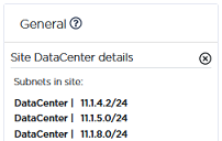
| 3 | Defining any subnet is unnecessary because you already defined (in the first Data Center ip|engine LAN) the subnet used by both hub ip|engines (11.1.5.0/24). Simply click the |

Also, the Next Hop address in the Subnet panel is useless because you will define the BGP Local Peer router ip address in the BGP parameter block (see below).
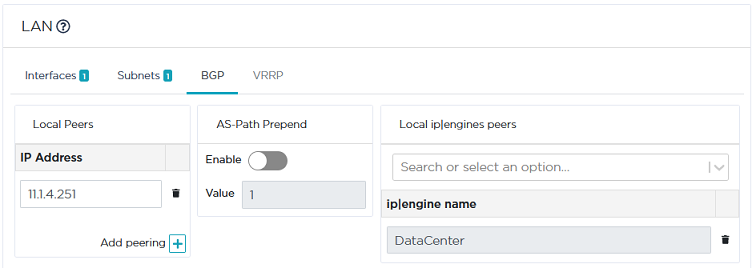
| 4 | Select BGP as LAN Routing Protocol, click the BGP tab and the Add peering icon |
The Data Center ip|engine exchanges its routing tables with the local router using iBGP.

| • | Enter the IP address of the BGP local peer (11.1.4.251). |
| • | Validate your settings by hitting the Create or Update buttons. |
| 5 | For high availability, define the master ip|engine through which traffic routing has priority over routing through the backup ip|engine. If you want the first ip|engine (DataCenter) to be the master, set its WAN1 and WAN2 Preference values to 200. To specify the second ip|engine as the backup ip|engine (DataCenter2), set its WAN1 and WAN2 Preference values to 100 (default). The highest Preference value implies priority. |
If WAN Preference values are identical, the system gives priority to the highest IP addresses. By default, Hub Preference values and Spoke Preference values are the same for a specific tunnel; if you modify any Spoke Preference value, it is automatically edited on the related Hub.
Validate your configuration.
| 6 | In the Network -> Advanced Configuration window, add the 'DataCenter2' hub ip|engine as Time Synchronization Server. Then click Update. |


